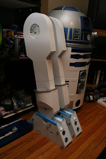
I was able to get some work done on the outer legs last night. I re-drilled the bolt holes to attach the foot motor holders and assembled the holders to the legs as a test fit. I'll have to take it apart to assemble the foot drives, but for now, it's looking more like a droid leg.
I also started cutting parts that will eventually become Artoo's center leg. I have plans on how to build the assembly into the frame and I'm currently sourcing materials (aluminum!!) to do this. If this works out, I'm also looking to have some custom parts machined to reinforce the shoulders and mounting assembly.
Over the weekend, while visiting friends, I was given a model of an Imperial Star Destroyer. It measures about 16" in length and the guy built his own stand to display it. He wasn't really happy with the paint job that he did, but asked if I would like it for my collection.
How could I refuse???
So my next "mini project" will be giving this ship a really sleek battle worn paint job. I'm researching now to find out where to start. I'm thinking of updating the stand, or possibly building a new one. I've gotta see what I have sitting in the scrap pile at home....
Monday, March 22, 2010
Tuesday, March 9, 2010
Ankle Cylinder Tutorial part 3
Continuing on from the last update, I have trimmed the excess material off of the cap. I used a utility knife to do so. After a light sanding, the part was smooth with exception of the end of the PVC tube that chipped away when I cut the tube. That will be filled in with glazing putty later on.
I measured out the width of the tab. This area needs to be cut out. The semi circles are then glued in place around the tab. When dry, a light sanding will prep for the glazing putty.
Another two coats later and some drytime overnight, the aluminum color is in place. I'm going to let the part rest and cure for a couple days and then tape off to repaint the center a metallic blue.
I have completed this portion already, but to show you how to cut the tab that is glued to the end of the cylinder, I started with creating a template. I based this again from the blueprints for the cylinder, located in the files section of the R2Builders Yahoo Group. This template will cut 6 pieces. Using 3mm styrene that I had left over from scraps, I cut all 6 pieces, and glued them together in pairs. This gave me a total of 3 tabs. After the glue cured, I sanded the piece smooth in preparation of gluing to the cylinder cap.
Here is the tab glued to the end of the cylinder.
Next up is to cut the semi circles that add detail to the end of the cylinder. The diameter of the circle is the same size as the glued edge of the tab.
I measured out the width of the tab. This area needs to be cut out. The semi circles are then glued in place around the tab. When dry, a light sanding will prep for the glazing putty.
This is the part after the glazing putty was applied and sanded. The chips at the end of the PVC have been filled and sanded smooth.
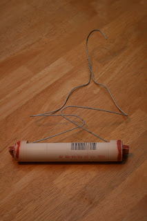
My wire hanger jig. After final sanding, the part is ready for primer.
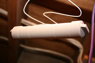
Prime coat.
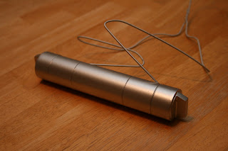
I've learned that very light coats of paint will bring out the most even coloring. This is after two coats of Rustoleum's aluminum color. You can still see the primer coat under the paint.
Another two coats later and some drytime overnight, the aluminum color is in place. I'm going to let the part rest and cure for a couple days and then tape off to repaint the center a metallic blue.
With an even coat of glazing putty, you can't tell that the tab is actually two pieces glued together.
Friday, March 5, 2010
Ankle Cylinder Part 2
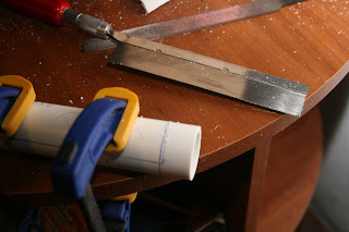
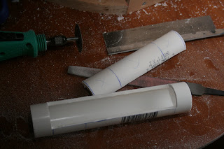
Time to start cutting into the cylinder. For the two cross cuts, I used an Xacto razor saw. This is a very thin kerf and very precise cut, as I don't want to cut too far past my end points. The thin kerf will allow me to use Bondo to clean up any over cut without filling in a larger gap, such as the kerf from the Dremel cut off wheel.
For the lengthwise cut, I used a rotary tool with a cut off wheel. I can't stress this enough - PVC is very gritty when being cut with this tool. Wear your glasses and a dust mask, and expect a pretty good mess when you're done. I've heard a lot of discussion of Dremels burning out. PVC is pretty easy to cut, just let the blade do the cutting.
The next part is to cut a guide line for the grooves. Again, I used my razor saw for precision.
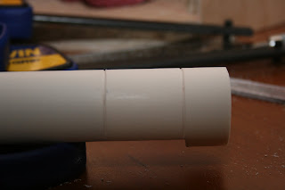
Once the guide lines are cut, I used a flat file to create a V groove. Using the corner of the file, cut in long smooth movements to keep the depth even. I had to rotate the cylinder several times to complete the groove around the PVC tube. Be careful and let the file do the cutting as PVC is soft enough to cut through all the way if you apply too much pressure. When you're done with this step on all of the grooves, clean up the entire part with some sandpaper. I recommend 220 or finer.
Close up of the V groove. This was prior to me cleaning up the groove with some light sanding. The actual cut is very straight.
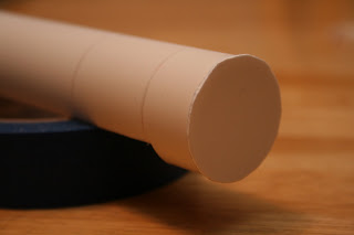
The last step for tonight is to cap the ends. Since I have leftover scraps of .040 styrene from my skins, I traced the PVC tube end on the styrene, cut and glued. I have been using Amazing Goop for plumbing. It sets in about half an hour and when it cures, it's near impossible to separate the two pieces. Make sure you have good ventilation when using this stuff - it's pretty potent!!! Oversize the cap a little, this will be trimmed with a utility blade after the glue dries.
These steps took about an hour to complete to this point. Let the part sit and cure. Next up, the tabs on the end of the cylinder.
For the lengthwise cut, I used a rotary tool with a cut off wheel. I can't stress this enough - PVC is very gritty when being cut with this tool. Wear your glasses and a dust mask, and expect a pretty good mess when you're done. I've heard a lot of discussion of Dremels burning out. PVC is pretty easy to cut, just let the blade do the cutting.
The next part is to cut a guide line for the grooves. Again, I used my razor saw for precision.
Once the guide lines are cut, I used a flat file to create a V groove. Using the corner of the file, cut in long smooth movements to keep the depth even. I had to rotate the cylinder several times to complete the groove around the PVC tube. Be careful and let the file do the cutting as PVC is soft enough to cut through all the way if you apply too much pressure. When you're done with this step on all of the grooves, clean up the entire part with some sandpaper. I recommend 220 or finer.
Close up of the V groove. This was prior to me cleaning up the groove with some light sanding. The actual cut is very straight.
The last step for tonight is to cap the ends. Since I have leftover scraps of .040 styrene from my skins, I traced the PVC tube end on the styrene, cut and glued. I have been using Amazing Goop for plumbing. It sets in about half an hour and when it cures, it's near impossible to separate the two pieces. Make sure you have good ventilation when using this stuff - it's pretty potent!!! Oversize the cap a little, this will be trimmed with a utility blade after the glue dries.
Thursday, March 4, 2010
Ankle cylinder
I finished the first of 4 ankle cylinders. I started the layout for the second cylinder and hope to get some work done on that one this weekend. This is such a simple piece to construct for those who are building from scratch. I saw this done on Dan Baker's build site, and gave it a try. I'm very happy with how it turned out. There are a few minor flaws, as in just about all scratch built pieces, but this again adds character to my build.
As I build my second cylinder, I'm going to document my progress as a tutorial. First up, aquire the material. I picked up a pvc clean water pipe, 1" schedule 40 from Lowes for $1.58 for a 5 foot length. The outside diameter of this pipe is almost dead on for the diameter of the cylinder. For anyone scratch building, this is about as close as you're gonna get. I cut each cylinder to 6.5 inches, based on a drawing that I downloaded from the group files archive, and started measuring. You can see that I have measured and drawn out my guide lines for the grooves and the cut out area. This area will allow the cylinder to recess onto the ankle. Next update will show the cut out area, and the process to recess the grooves.
Subscribe to:
Posts (Atom)

