Thursday, December 16, 2010

It's been a while since I have had time to update this site.  I have done some work over the last month on some details, but nothing earthshaking just yet.

December marks my 3rd anniversary as a member of the R2Builders group. 

I ordered Chani's styrene skins and started working on the fronts.  It took me 3 months to layout and cut my first set of skins, and two weeks to get the front skins cut from Chani's part run.  I didn't even use a straight edge - the scored lines in the styrene were all I needed to keep the blade in line. 


The boosters are now glued to the legs.  I have been debating whether to replace these or not and decided to put off building the new legs for the moment.  I will eventually replace them (and the boosters as well, since I will need a second set anyway...), but for now, I feel that I have reinforced them well enough for them to hold strong. 

I have test fitted the horseshoes and plan on gluing those as well.  I don't have much of a choice as I don't wish to drill into the leg structure.  I'm finishing off the second horseshoe with Bondo before giving it a paint coat.  Artoo's next public appearance is in the end of January, and I am hoping to have him looking a little closer to finished by then.  Still have a ways to go and I estimate another year or two before I'll call him "done".  Below are some recent pics:


Here are a few pics from Artoo's first public event at the Buffalo Library. 


Photo by Dan Malcomb. The North Ridge/Fan Force


Wednesday, October 20, 2010

Dome Drive is working!!!!

Well, I didn't think I was going to get this part complete until after Christmas, but I was able to get the necessary parts in time for Halloween.  I'm running an IG32 motor for the drive and the Syren 10a motor controller to control direction and speed.

I had to build a brace to mount the motor to and I based my part on Calvin's motor mount.  Still getting some slipping when I change directions suddenly, but overall, the setup was very easy and I'm happy with the progress, and it's just in time for my first public event on Saturday. I have to clean up my wiring mess  before then as I won't have a back panel in place and the rear door is off the frame.

Anyway....  Here's a short video of the progress. 


Tuesday, October 5, 2010

12V Power is operational

With a 3 week deadline before my first outing with Artoo, I'm trying to get things finished up with dome movement and animation features.  I've been getting some practice driving and took the droid outside for a spin around my driveway a couple weeks back. 

Over the weekend, I was able to get the 12V power up and running.  Power is being distributed through the Rigrunner box.  My amplifier is powered directly from the Rigrunner, power is also fed to the 12V distribution board and on to my 12ch relay.  I still hear the circuits clicking as they close when triggered.  Not sure if I'll be able to do anything about that, but hopefully it won't be noticed too much with a crowd of people around him. 

I love the LED's on the back power panel and i have been driving him around tonight in a dimly lit room.  For the first two outings, I won't have the back door completed so the back panel will be exposed.  This can be a cool thing and a potential disaster as well.  I like the looks of the wiring and the indicators and think it's a good idea for people to see what he looks like inside, however, keeping control of people who can't seem to keep their hands off stuff could lead to problems.  I think for the first outing at least, he's gonna be behind a barrier of sorts.  I'll roll him close enough for people to see and touch, but be able to back him off if people get too grabby.

Anyway, here's the progress from this past weekend:

Up close view of the panel


12V distribution board lit up.  The board to the lower right is the Sabertooth motor controller, running on 24V power.


My VEX transmitter with the 12ch relay transmitter attached.  I used industrial strength Velcro to attach the two together.  The 12ch transmitter controls the programmed sounds.


The whole set up.


Monday, September 6, 2010

Test Drive - My Artoo's First Steps

First and foremost, a very big THANK YOU!! to Calvin Thomas for spending two hours over email tonight helping me troubleshoot and configure the R/C functions.  I think it came down to one setting on the dip switch box that really made the difference.

I started this blog on Labor Day two years ago.  Two years later, I finally reach the first major milestone in my build.   After several hours of bench testing and re-wiring, reconfiguring etc, here are the results:

Prepping for first run.

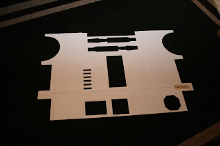
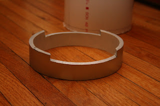
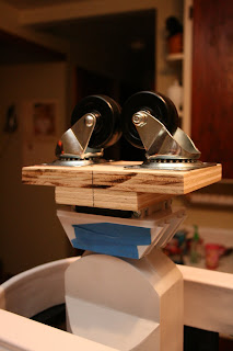
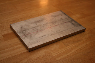
The past two weeks have been kinda crazy with work, home, preparing my kids for the school year, etc.  I found some time to continue prepping R2 for a first run with R/C.  Before I could do anything, I needed to strengthen some areas and reduce the side to side wobbling.  This wasn't coming as much from the shoulders as it was the ankles.  I did need to fill the shoulders out, which also adds stability to that area.  After several failed attempts at cutting these circles out of wood with a Rotozip, I decided to go back to the old jigsaw method, and had these cut out in no time.  These parts sit snugly inside the shoulder between the shoulder hubs and the outer PVC shoulder.  I haven't fastened these to the leg permanently as I'm still unsure if I will keep these legs for this droid or replace them with A&A legs and save them for droid number 2.  Either way, they give strength to that area and I'm happy with the results.


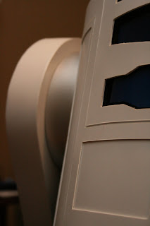
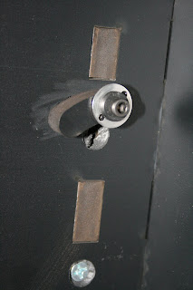
I cut and laminated the ankle locks.  These parts restrict the movement of the foot at the ankle and keep the foot relatively level.  They also prevent the foot from turning inward, under the body.  I also found that I needed to add a piece of .040" styrene on the inside ankle where it attached to the foot.  This also prevented unnecessary side to side movement in this area.  You can see where my first cable pass through hole was placed.  Looking at the plans for the ankle, there was a hole drilled there and I didn't find any real explanation for it.  Unable to bend the cable through there, I consulted my fellow builders (thank you Calvin!!) and re-drilled the hold at the bottom.  This connection is temporary, as I will need to re-route the cable in the foot to better conceal it before covering the foot with the foot shells - but for now, it will do.


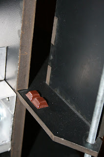
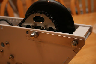
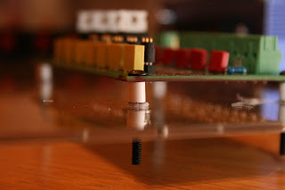
I had these parts leftover for years.  These are rubber bumpers that I got somewhere... but I find uses for them.  In this case, this will provide stability, and little cushion for my electronics panel.  These bumpers will keep the panel from sliding in or out of the frame.


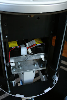
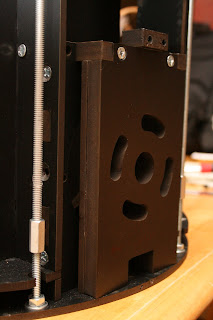
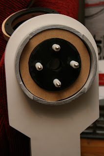
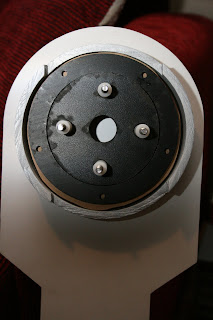
I needed a solution to hold the electronics panel in place on the frame, but make it removable as I will need to access the battery compartment behind it.  I used scrap pieces from when I purchased the frame (this is a kidney shaped piece that is 1/2" thick, originally a cutout from the shoulder hubs...).  After drilling a hole large enough to fit and end of a T-nut, I JB Welded the T-nut  and glued the whole thing to the frame.  Rubber washers will help reduce some of the shock where the bolt passes through the panel.


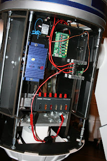
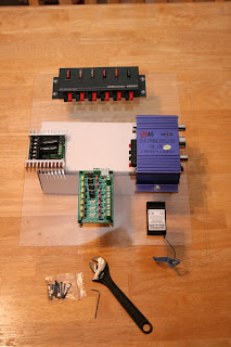
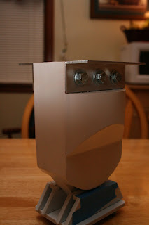
Electronics panel installed.  This is set up only for the foot drives.  I have an in line fuse placed on the 24V power cable (30amp fuses).  Probably won't do much as I only expect to max out at 14-15amps at start up, but it's there none the less.  Since I don't have a 12V battery yet (still on my "to order" list....), the Rigrunner fuse box at the bottom is left disconnected.  I routed the cabling from my radio receiver to run 5v power from the foot motor controller.  This is just for testing purposes as once I receive a 12V battery, power for the receiver will be drawn from the 12V power distribution (green board at the top/center of the panel...).

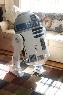
I just put batteries in my transmitter and programmed channels 1 and 2 as "mixed" signalling.  Just need to find time to test the systems.


Friday, August 20, 2010

Installing components

Now we're starting to look like a robot! 

I installed the 12 channel relay into the frame.  The circuit is housed in a foam core box that will add insulation, as well as an easy way to remove the whole piece for maintenance.  The board is adhered with Velcro to the back panel of the box, and the box is also adhered with Velcro to the inside of the frame.


I pulled these speakers from an old stereo system.  I tested with these speakers when I wired up the 12ch relay a few weeks back.  They sound great!!  Very clear, and much louder than the cheap speaker that came with the Thinkgeek shirt.  The speakers will be behind the vents on the front of the droid.

I also came up with a solution to house the batteries.  I used angle stock aluminum and JB Weld and created a holder.  The batteries fit perfectly and it allows three 12V batteries (2 connected in series for 24V for the foot drive, and one single 12V feeding the Rigrunner board to run everything else).


I'm currently wiring the power/drive board and will *hopefully* test the drive soon.  I ran into some issues with the Anderson power pole connectors and the 14guage zip cord that I purchased.  The insulation was in the way as I was putting the parts together (30amp power poles).  It appears to be just with this particular wire as the 12 gauge zip line that I have goes together fine.  I switched to 45amp power poles for anything that I'm using the 14 gauge line to connect and those fit together nicely.  More to come on that with the next update.

Tuesday, August 3, 2010

Shoulder Hubs Installed.

I spent time over the weekend cutting hubs from a piece of 6" water pipe that was given to me a while back.  I cut notches to fit around the frame upright and had originally intended to glue them to the legs, but I'm thinking otherwise right now.  I have been thinking for some time about upgrading or replacing parts.  He's not even complete yet, but I'm not really happy with some of the work I did.  I have mentioned about replacing the skins.  I'm not happy with how they are cut, and being my first part that I made from styrene, they are a little rough.  A group member (Chani) is offering semi cut skins for a good price and I may grab a set of those.  I am also considering replacing my styrene legs with the A&A legs.  I plan on keeping the styrene legs for a possible (probable...) droid number 2, so they're not going to waste.

In any case, the shoulder hubs are on, and even though they aren't glued, they still look pretty good.


You can see how rough the skins look.  Granted, these have not been sanded yet and that will improve the appearance, but I cut the area around the utility arms wrong and have never been satisfied with how it looks. 


The full droid so far.


Thursday, July 29, 2010

I added some more LED's to the front logics.  I can't fit all 80 diodes due to the amount of wires looped in.  I may opt to replace these logics with a circuit board, but for now, it's pretty convincing.  In the pic, you can see some empty holes where I don't have diodes placed.  I'm hoping to squeeze one more string of lights into the logics, without breaking a chain....again...   I also plan on filling any leftover open areas with an unconnected diode, allowing the light from the neighboring LEDs to reflect through it.

In the below picture, you can see the gap I have to fill between the legs and shoulder of the frame.  I cut and glued up some leftover styrene, about 1/4" thick, around the shoulder area to add stability and strength.  I have two circular pieces from the frame which will be added as spacers and I'm hoping to either have additional parts made or will cut some plywood to fill in this space, roughly 3/4" thick.  This will add additional strength in the shoulders by reducing the amount of potential sway.  I strengthened the shoulder on the frame and moving Artoo around the house, I don't find much movement in the shoulders as he is right now.  The reinforcement will only add strength.  Additionally, I have 6" water pipe that will give me the proper diameter for the shoulders.  The water pipe will not add any real structural value and will more than likely be glued in place to the inside of the leg, covering up the shoulder hubs.


Wednesday, July 21, 2010

I finished the modification/construction on the feet.  The last piece was to create a bracket to hold the axle and chain tensioned.  This is one foot.  I have yet to attach some Anderson power poles to the wires on this foot.  The other foot has then connectors attached already.  For all intents and purposes, this part is done until I get the shells to cover it.  (Note - The bottom plate that was removed over the motor area will be re-attached before the foot is mounted to the ankle).

Friday, July 16, 2010

Electronics Board Layout

Ok, so it's not the most complex board to ever fit a droid.  Doesn't run a ton of gadgets, not going to repair my truck while on a trip, and certainly not going to fire jets on his outer legs and make him fly around a room.

But then again, I can't exactly leap tall buildings in a single bound either....

What this will do is provide and distribute power to different areas of Artoo.  These are only some of the boards that will be installed.  From the top and clockwise: RIGrunner 4005 series fuse box, Chinese made 180watt amplifier (how true, I don't know, but I've heard it's loud...). Multiplex IPD 7 channel radio receiver, R2 Builders club made 12V power distribution board and my Sabertooth dual channel drive board (to drive the feet).  Still need to order the Syren10 controller for the dome, which will find a home near the Sabertooth.  Although the board appears right side up, the board will be mounted to position the RIGrunner at the bottom.


I couldn't find any circuitboard standoffs so I made my own from styrene tubing found at a local hobby store.  I cut them to 1/4" lengths to give some cooling underneath the boards.


I went a little artsy-fartsy with the photos...  I miss shooting creatively and just got in the mode to do a little "product shooting" last night.  Here's the 12V power distribution board made for the club.


And a close up of the RIGrunner 4005H.  The fuses came with the unit, but I'll need to change them to meet my needs.  A nice feature of this board is if/when a fuse blows, there is an LED indicator in the board to alert me to which fuse to replace.  Nice piece if equipment, used by the amateur radio operators to run their stations.


Monday, June 7, 2010

Artoo On His Feet

This is work that I have done over the last two weeks.

During the week, I measured and built the center foot. I had to come up with some creative ideas to mount the casters to the plate since the mount to the ankle kind of overlapped a little. All in all, the foot is attached securely.


You can see a little heat damage on the ankle.  Fortunately, this won't be seen when the droid is right side up.


I've had to make some modifications to the frame in the shoulder area. I plan on replacing this area with aluminum shoulder plates, but until I set aside money, I won't be able to do that. In the mean time, I modified and laminated the 1/4" JAG plate that I wasn't using, to the existing 1/2" JAG plate to create one plate that is 3/4" thick. I'm betting that between the thickness of the material and the laminated parts, the shoulders should be strong enough for now, until I can replace them with aluminum down the road.


Last night, I attached the legs to the frame. I still don't have the foot motors or drive wheel installed, so I had to level the outer feet on some hardcover books. I haven't checked the angle on the legs, but I'm guessing I'm pretty close. I won't be able finalize this until the drive system is installed.

Just for fun, I put the dome and front skins on. 


Sunday, May 23, 2010

Center foot plate installed

This weekend, I started drilling the aluminum plate.  Today, I installed the bracing and leveled the plate in the frame.  I still have to drill the holes to line up with the bracing on the center leg, and that should be done later this week.  Next steps in line, I need to measure and design the mounting for the castors on the center foot.  I need to install the foot drive (motor, wheel, chain and tensioners) on the outer feet.  Lastly, I need to strengthen the shoulder area on the frame as well as the leg.  Once this is done, I can start wiring and bench testing the motors and remote control. I'm hoping to have Artoo rolling by early summer.


Monday, May 17, 2010

Braces, Sounds, and a Big Ol' Piece of Aluminum.

I had some time this weekend to do some work. I picked up some aluminum to start structuring out the center leg attachments. This will be bracked to the bottom plate using 1/8" thick angle bar stock. I machined out the holes needed to attach the brace to the frame and leg and got it bolted to the leg. It's a nice tight fit and the braces are not coming loose at all. The top is very level where it will attach to the bottom plate.


Speaking of the plate, thanks to the generosity of a member in my church, (Thank you Tim W!!) I now have a 1/2" thick piece of aluminum cut to the dimmensions to fit perfectly in the bottom of my frame. This will provide support to the frame, as well as a sturdy base for the center leg to attach and a place to sit batteries low in the body. I have some machining to do on this part to get it in place, but should hopefully have time this coming weekend to work on it.

I spent yesterday working on the Thinkgeek soundboard. Last week, I pulled the wired controller apart. Yesterday, I spent time working with my father in law wiring and testing the unit. I cut the attached speaker off and tested on a small 3" stereo speaker that I had in posession. I plan on wiring two of these in series to run at 8 ohm. The speaker was plenty loud without the amp, but I may still install the amplifier to better control the sound.  This is what it looks like currently.  I removed the speaker and cut the ends of the wire to prevent shorting.  I will have to add tab connectors to attach to the speaker.  Power will be supplied from a distribution board to run the 12ch. wireless.